Rebuilding the front suspension & steering linkage
Text and photo's are taken from the Mopar Muscle Magazine website.Rebuilding The Front Suspension With PST
From the February, 2004 issue of Mopar Muscle
By Steve Dulcich
Photography by Steve Dulcich
Some words from Crazyman
The people from this article using a PST kit, but you can, of course, use other brands. I, for instance, use MOOG parts, Energy Suspension polyurethane rubber parts and Rare Parts pitman arm (strangely enough Moog doesn't make pitmans).Introduction
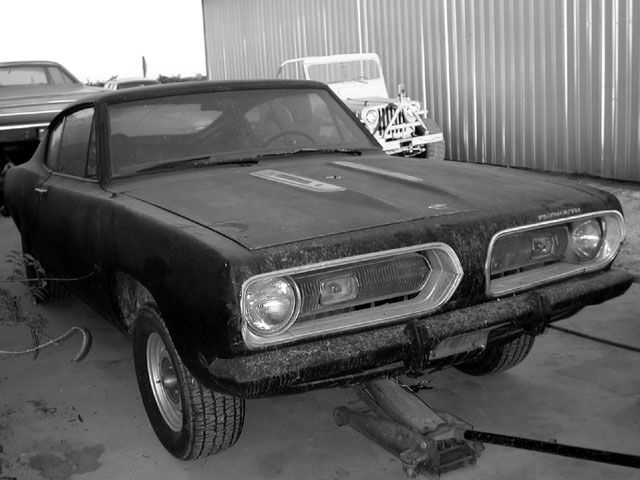
Quite some time ago we introduced our ragged '68 Barracuda fastback. The tired old beast was put on the road with a minimum of wrenching-just enough to get it going. With its rat-rod flat-black primer and stripped-out interior, it was the perfect machine for slummin' in style. We got the itch to make it a little better though, and out came the well-worn 318 for a buildup. With the engine out, it seemed like the right time to get other mechanical matters up to spec. Though the rear suspension had been thoroughly rebuilt, up at the front, things were downright sloppy. With more power on its way, it was time to bite the bullet and do a full rebuild of the front end.
Suppliers, such as PST, offer complete suspension rebuild kits, providing all of the normal replacement components in one box. With a kit, the front suspension and steering can be stripped out and fully rebuilt to as-new freshness. We strongly prefer this comprehensive approach, rather than replacing parts piece-by-piece. PST offers bushings in either stock rubber or their proprietary PolyGraphite material. We opted to get a mix of the two, going Poly for the strut rod and upper control-arm bushings, while retaining rubber for the lower control-arm pivot bushing. New upper control-arm adjusting cam-bolts were provided in our kit, and we noted that the design had been beefed-up considerably from the replacements offered a few years back. To complete the parts selection, we ordered a complement of components to renew the steering linkage, including all the tie-rod ends, a set of heavy-duty tie-rod adjuster sleeves, as well as the pitman and idler arms. Rounding out the kit for our application were new ball joints and fresh rubber bumpstops to replace the battered originals.
Long term, we really aren't sure of what direction we want to go with this fastback fish. On one hand, we like the idea of building a fast drag car, taking cues from the SS/AA package cars that made this particular body style famous. Big-block, full cage, Hemi scoop, and 9-second performance-it would definitely make a statement. On the other hand, a nice fastback 'Cuda street machine with a warmed small-block, overdrive tranny, and a few chassis upgrades would be tough to top as a driver. We're leaning towards the first option, and as a step in that direction, we tapped Competition Engineering for a set of 3-way adjustable drag shocks. We may change directions before it is all said and done, and welcome your comments in helping us decide.
Step by Step
Although this article is about an A-body, it's almost the same for a B-body.Mouseover the images for original size.
Rebuilding Front Suspensions With PST - Suspending Dilemma
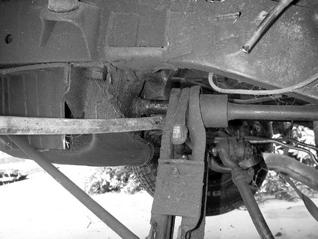
Our dog-tired '68 Barracuda had a well-worn front suspension. One of the best upgrades on any old Mopar is to freshen the underpinnings up front with a complete rebuild. We had the engine out of this car for a rebuild, so it seemed like the right time to go through the suspension.
Front End Suspension
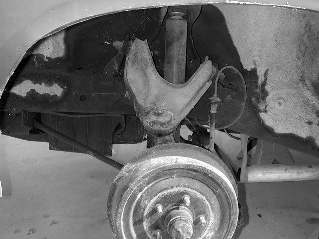
The front end of this original 318 machine was the basic package, including drum brakes and no sway bar. We may follow through with higher performance upgrades later, but for now, we just needed to eliminate the unnerving wiggle in the loose components. Rather than going after the parts replacement piece-by-piece, it's best to just order a kit and replace all of the wear components.
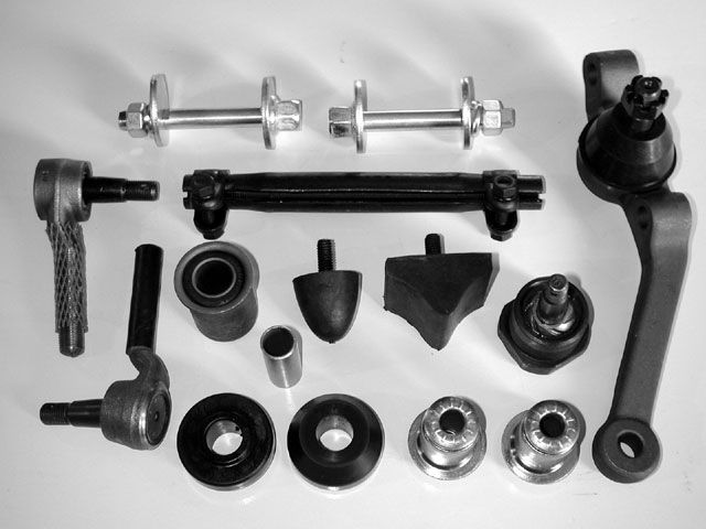
PST Kit
To take care of business, we ordered a complete kit from PST, and upped the ante with PolyGraphite bushings for the upper control arms and strut rods. We decided to use the stock-style rubber bushings on the lower control arms. These parts will basically replace all of the wear components (one side shown), including the upper and lower control-arm bushings, tie-rod ends, upper and lower ball joints, strut-rod bushings, and camber adjusting bolts. We noted that the camber adjusting bolts have been upgraded from those previously offered; these were nice heavy-duty pieces. We also got fresh pitman and idler arms (not shown).
Relieve Torsion Bar Tension
The first step after securing the car on jack stands and removing the wheels is to take off the upper control arm bumper to
fully release all tension on the torsion bar.
Step two is to fully unwind the torsion-bar adjustment screws, located under the lower control-arm.
This will relieve the spring tension from the suspension.
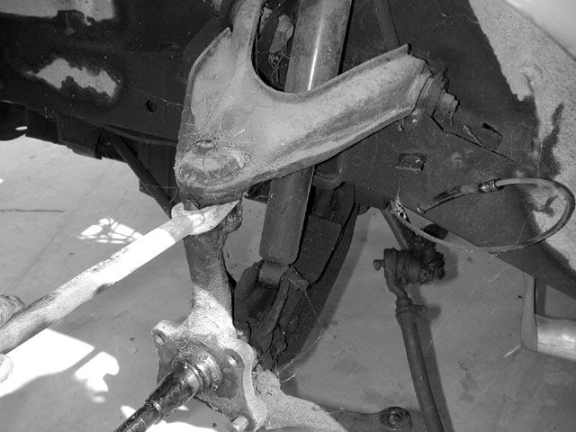
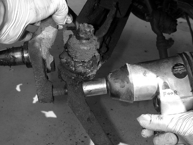
Tie Rod Ends
Since the tie-rod ends were worn out and will be discarded, we used a pickle fork to separate them from the steering arm. To use the fork successfully, always align it so that it is working straight back into the steering arm. otherwise the deflecting steering linkage will absorb the force.
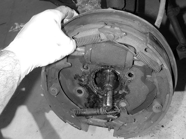
Remove Brake Drums
After removing the wheel-bearing nut, the brake drum was pulled off, followed by the backing plate with the brake assembly.
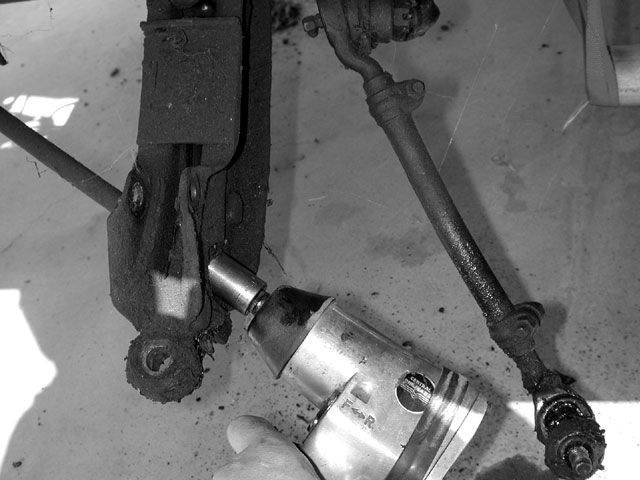
Upper Ball Joint
We used the pickle fork again to separate the upper ball joint. The upper control-arm was then unbolted and removed.
Remove Shock
Next, the shock was removed. It anchors to the lower control arm with a thru-bolt, and a bayonet through the inner fender apron.
---------------------------------------------------------------------------------------------------
It's better if you remove the shock absorber after you've removed the strut-rod and lower ball joint.
That way the LCA is less "wobbly" and it's easier to disconnect the strut-rod and lower ball joint.
Remove Spindle
The spindle was then unbolted from the lower ball joint/steering arm. One of these bolts in early A-Body drum-brake spindles, threads directly into the spindle. Note the rounded head of this bolt, and reinstall it in the same position.
Lower Ball Joints
Our handy pickle fork was employed once again, to quickly separate the lower ball joint.
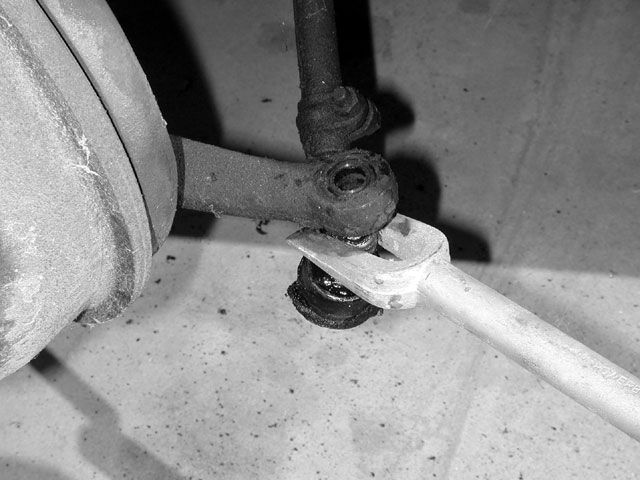
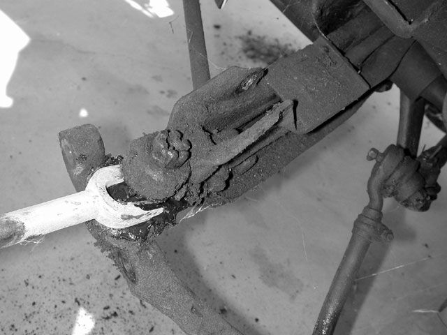
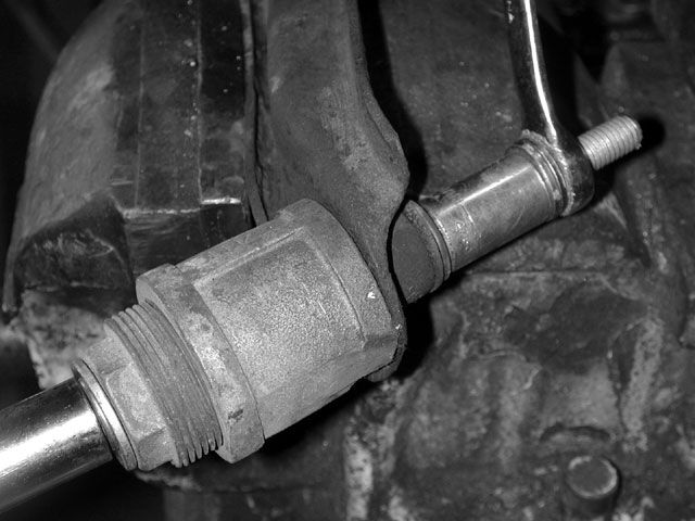
Front Strut Rod Nuts
The front strut-rod nut should always be removed first, then moved to the rear of the rod. The tapered seat at the rear of the bar keeps the bar anchored to prevent it from spinning when removing the front lock nut.
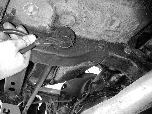
Rear Anchor
At the rear anchor of the torsion bar is a small wire retainer clip. Remove the clip to make way for removing the torsion bar.
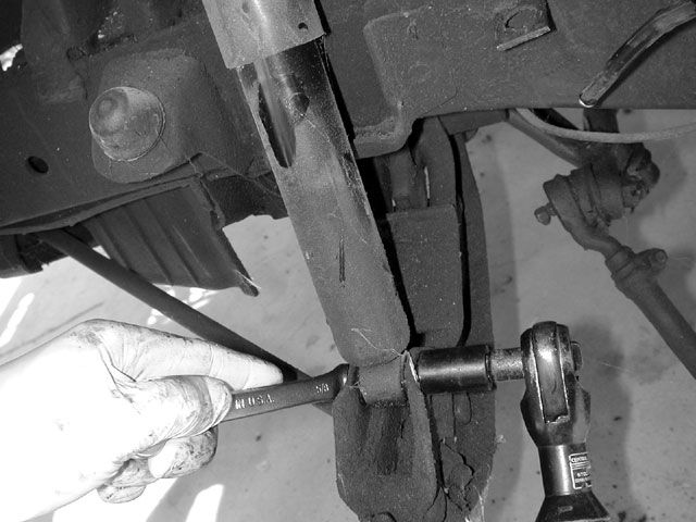
Remove Lower Control Arm Pivot
Since we are removing the control arm, there is no need for a special tool to remove the torsion bar. just remove the lower control-arm pivot-shaft nut where the shaft goes through the K-member, and then use a large pry-bar to wedge the lower control arm back. The torsion bar will slide back with the arm, and out of the socket at the rear crossmember. The control arm can then be tapped forward and off the bar.
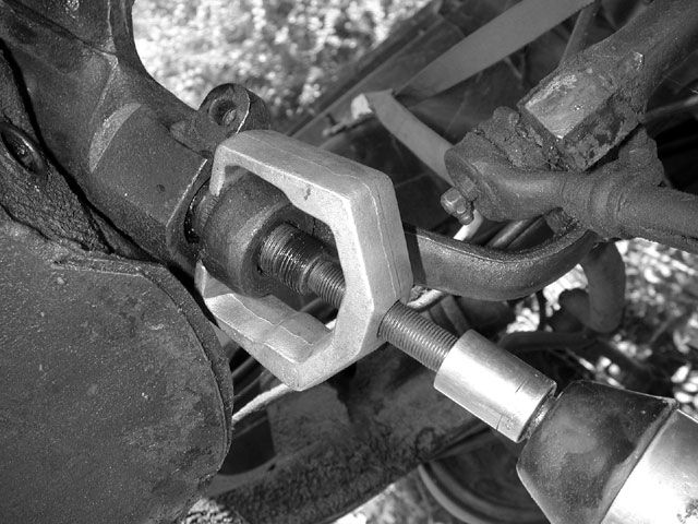
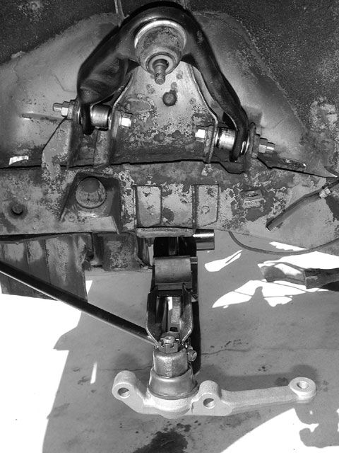
Pitman Arm
If the pitman arm is going to be replaced, a large heavy-duty puller will be required to get it free of the steering box. The idler arm simply bolts to the K-member, and the steering linkage can be removed as an assembly.
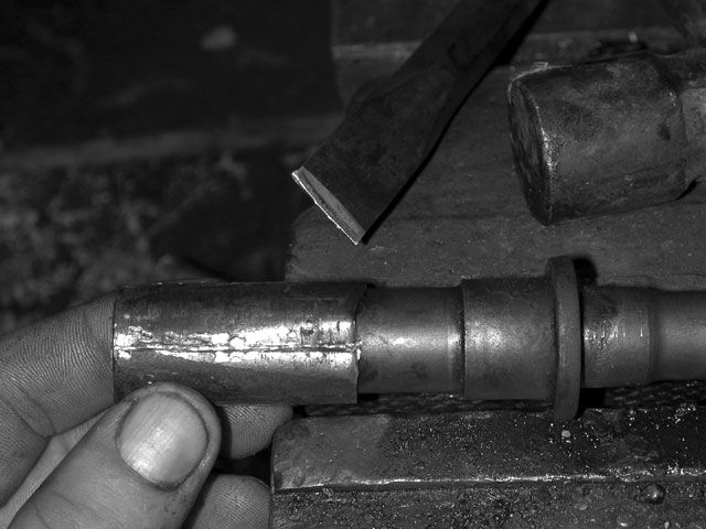
Pivot Shaft
Next, we stripped the lower control arm, pushing the pivot shaft out of the bushing from the back. The bushing shell will remain fixed to the shaft, but it is easily removed by striking it with a chisel, at 90-degree intervals along its length.
Lower Control Arm
We cleaned and painted the arm, and then pressed in the shaft and fresh bushing. With a new bumpstop and the torsion-bar adjustment hardware installed, it was ready to go back in.
Upper Ball Joints
The upper ball joints screw into the control arm, and require a special socket to remove. Be prepared-they are tight.
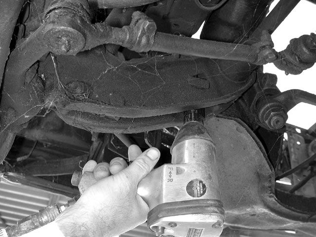
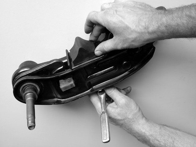
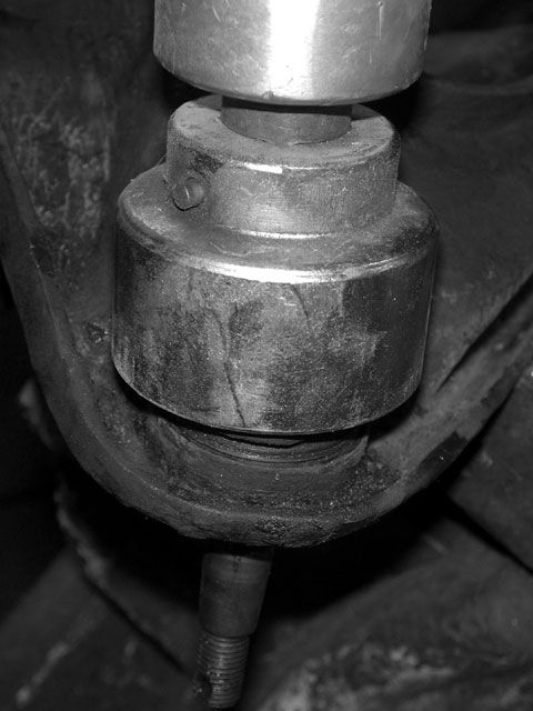
Remove Upper Control Arm Bushing
To remove the upper control-arm bushings, we use a 1/2-inch jackscrew as shown. The large pipe fitting to the left receives the bushing as it is pressed out, and is ground with a step to clear the flange at the edge of the control arm. The socket at the right pushes against the bushing as the screw assembly is tightened with a 31/44-inch drive impact wrench.
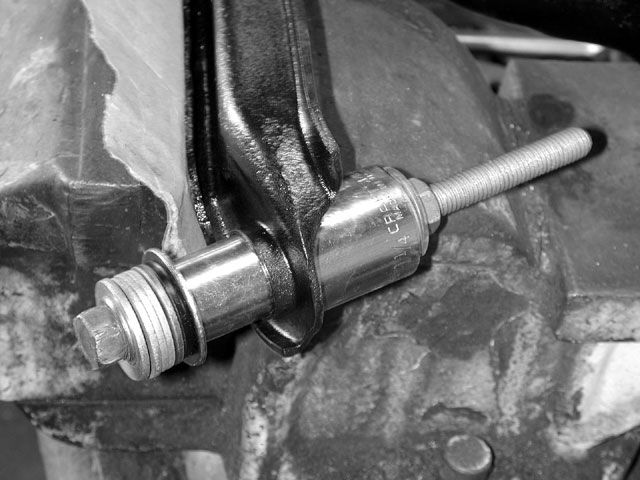
Large Socket
Installing the new bushings is done with a similar arrangement, this time using a large socket to the inside of the arm to clear the bushing as it comes through.
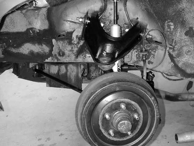
Camber Bolts
The upper control arm was bolted in with the new camber bolts from the PST kit, and swung up out of the way. Next, the strut rod was bolted to the lower arm, loaded with the rear half of the bushing, and the lower control arm was angled into position and bolted up. Finally, the lower ball-joint assembly was bolted in place.
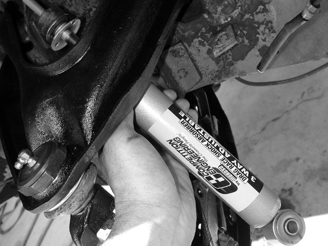
Three Way Adjustable Drag Shocks
Since we were planning on making a drag car out of this 'Cuda, we opted for Competition Engineering's three-way-adjustable drag shocks, which we set to 90/10, for the greatest rate of front suspension rise.
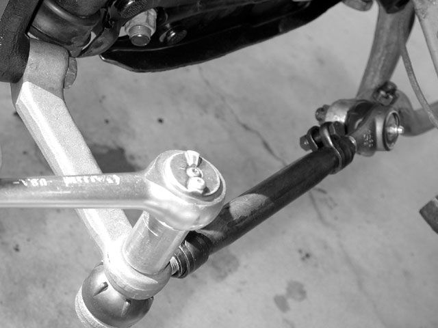
Steering Linkage
Installing the steering linkage is very straightforward; just install the pitman and idler arms, followed by the center link, and then the tie rods. We liked the new heavy-duty tie-rod sleeves from PST.

Front Anchor
With the suspension resting down against the bumpstop, and the front anchor of the torsion bar clocked against a fully unwound adjuster screw, the torsion bar should align and slide in easily with some light hammer taps from the rear.
Stock Drum Brakes
For now, we just reinstalled our stock drum brakes, finishing the suspension rebuild job. We confess to be itching to upgrade the brakes before putting the car back on the road or track.