My '67 Dodge Coronet 440 Sedan front end rebuild
After rebuilding the rear suspension and seeing what the rubbers from the springs and shackles looked like. It was obvious that the front suspension and steering linkage had to be rebuild as well. Maybe not the steering linkage, but if you remove the upper and lower control arms, you have to disconnect the steering linkage anyway, so why not doing a complete rebuild? So with that in mind, I've gathered all information I could find on the internet and bought all hardware and tools necessary for the job.Rebuilding the front end
The first step, removed wheel and grease-cap.

Outer bearing cone.

The empty spindle, removed wheel-, hub- and drum-assembly.


Disconnected tie rod from lower ball joint.

Spindle unbolted from lower ball joint.

Just before I separated the spindle from the upper ball joint.
See the enormous amount of dirt and old grease...

Spindle removed.
Upper ball joint removed.
The easiest way to do this, is with a special ball joint socket and an impact wrench/gun.
Because these ball joints are incredible stubborn and known knuckle busters!

Before you can remove the upper control arm, it's a lot easier if you open the special access holes in the side fender shields.
After these are opened, you can easily remove the cam adjusting bolts.

Upper control arm is removed.
The white dot with square hole is for the upper control arm bump stop.

My home made tool, to remove, and press in new, upper control arm bushings.
The piece of pipe, in the upper right corner, is used to press in the new bushings.
In this picture you see me pressing out an old bushing.

The left upper control arm is finished.
New bushings and a new ball joint. The A arm is only high pressure washed. So it's more or less clean.
For extra protection I painted the UCA with an anti rust liquid.

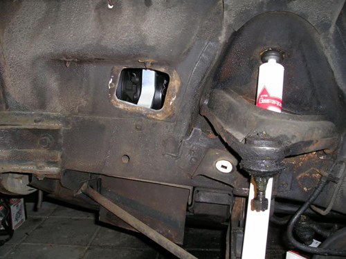
The shock is removed. It is better if you leave the shock until you've removed the strut rod and lower ball joint.
Otherwise everything is dangling in the air, while you are removing parts. It's much more stable with the shock.

The lower ball joint is removed.

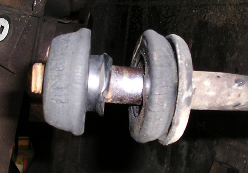
Strut rod removed. See how bad the bushing is.

After removing the wire retainer clip at the rear of the torsion bar and the lower control-arm pivot-shaft nut,
you can use a large pry-bar to wedge the lower control arm back. Here you see the control arm is already off the pivot shaft.
the pivot shaft is still in the k-member, on the left.

The pivot shaft and the control arm are removed, on the right you see the hex end of the torsion bar

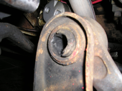
You can see that the control arm bushing is totally gone!

The bushing shell will remain fixed to the shaft, but it is easily removed by striking it with a chisel
at 90-degree intervals along its length.

And it worked! The inner bushing shell is off.

So finally, the bushing outer shell is out of the lower control arm!
It took some time and effort. (See HERE how you can do this without a welder
and shop press AND in less time it took me, for the one you see in the below picture)

My DIY bushing press. Here is the privot-shaft pressed into the bushing.

The pivot-shaft is pressed into the bushing.
Hmm, it's looking familiar... A German stick grenade.

The same construction as above, only this time with a larger diameter pipe, to press in the bushing.
I have to say, if I had use of a shop press after this is finished, I buy one. It's probably (because I don't have one)
a lot easier to press in the bushings. But must the occasion rise, I buy one.

The pivot-shaft and bushing are pressed into the control arm.

Remark:I couldn't press in the pivot-shaft into the bush of the rightside. I do not know why.
I called a friendly garage and I could use their shoppress. So i've pressed in the pivot-shaft and the combination pivot/bush
into the controlarm with a shop press. And I can say now, maybe I should have bought a shoppress. It's incredibly easy and fast!
I realize that this is always the case, with the right tools the job's done in no time.
Old pitman arm is of the shaft.

Do your self a favor, buy or loan a pitman arm puller. Don't use a normal puller, because those tend to slip off the pitman.
See image below:

New pitman arm

Installed strut rod, with new bushings, control arm and shock.
Changed the KYB shock for Monroes.
It's better if you install the shock after you've installed all other parts! Otherwise you hit it with your tools and you can't wrench well.

Installed lower ball joint.

Installed tie rods and sleeve. The Moog sleeve is much beefier than the original.

Installed upper control arm, it's better if you did not installed the shock absorber.
That way you can install the cam bolts a lot easier.
After that, i've connected the spindle to the upper ball joint.

Installed break drum assembly to the lower ball joint and spindle.


Everything bolted together, spindle, lower- and upper ball joints and upper control arm.

Almost done with the left side. Torsion bar is slided back into the LCA.
 The old dust boot has to stay for the moment. This has to be done on a hydraulic lift.

Although this isn't part of the front end, I thought, why not? So, I installed new bearings.
The bearing cups are out of the brake drum. Ready to put in the new ones.


New bearing cups are in the hub. Front bearing cup.
 Rear bearing cup.

The drum is on the shaft again. With new bearings and seal. All nuts are tightened when wheel was on the ground again.
All nuts (shock, pivot-shaft & strut-rod) are torqued to spec.

Oops, I almost forgot to install the upper control arm bump stop!

So, the last pieces. The idler-arm. This is the old one. It gave me a headache to remove it! No puller, I have, did fit.
So I had to use the picklefork.

This is the new idler-arm. As you can see the old idler had no grease fittings. This one, from Moog, has.

So this is it, all is done. The left- and right-side are the same apart from the pitman-arm and the idler-arm.
There is only one thing to say: Happy wrenching!
Some remarks & observations.
#
Please keep an eye on where the hole for the cotterpin is located. Especially with the upper ball joint and spindle.
Worst case is when the cotterpin can only be inserted from one side, towards the spindle.
This way you can barely bend the legs of the cotterpin.
#
The removal of the idler-arm is a little different than all other ball joints. All other joints have a dust cover,
so when you insert a puller, there is enough room for it.
Not with the idler-arm. The idler doesn't have a dust cover. Only a soft rubber ring.
After you remove this rubber ring, there is, maybe, not enough room for a puller. The distance between idler-arm and steering linkage
is about 1/8 inch (3mm). I don't have a puller which will fit, so i had to use my picklefork.
# Don't forget the wire retainer clip at the rear of the torsion bars. These are the cotterpins for your torsion bars, so to speak.
# Oh yes, make a appointment with a alignment shop. This is absolutly essential!
----------- Some remarks after driving with the new bushings -----------
Driving with the new bushings is great. Especially when I drive a very bumpy road, you could hear some very nasty metal to metal
noises. This is gone now. That was probably the lower control arm bushing, or better said, the lack of a bushing. The pivot shaft was hitting the lower control arm.
Now I only hear some rattling of the interior, which is normal.
When I take a corner at high speed, the car feels good. Overall the drivability is much better now. But the Hotchkis rear leafsprings and the
Monroe rear coil-over shocks together with polyurethane bushings help a lot!