My 318cui gets a hotter camshaft
For this cam swap the engine stays in the car. But before you even get close to the camshaft, there is a lot to disassemble. Which you will see in the pictures below. The new cam is an Edelbrock Performer Plus with hydraulic flat tappet lifters. This cam gives more torque from the low-end to the mid-range. Which is great for street use. The timingset (chain & sprockets) will be replaced as well. I hope I can replace the lifters without removing the intake. If that's not possible, I've a second set of cheap gaskets, which I need to install the old intake again, for the camshaft break-in.
Here we go!
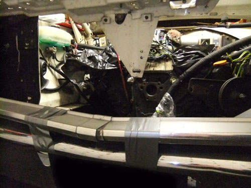
The alternator, radiator, fanshroud, fan and waterpump pulley are removed.
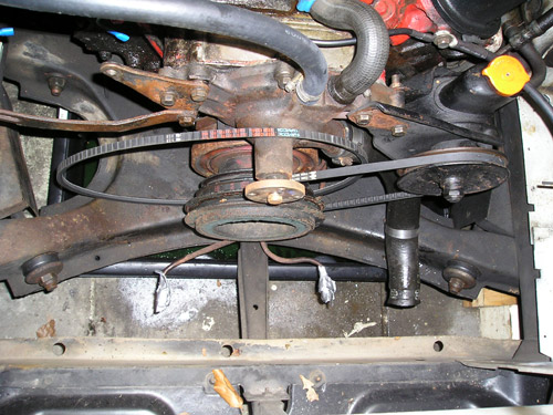
I had to cut the bypass hose. It wasn't flexible anymore.
A big setback, one of the waterpump bolts broke.
And you can see (on the right side) the powersteering pump hanging on a couple of wires. I didn't want to disconnect it.
(I couldn't remove the broken off bolt. So I had to buy a new timing cover).
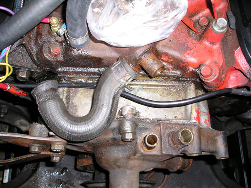
Crank pulleys and crank bolt are removed.
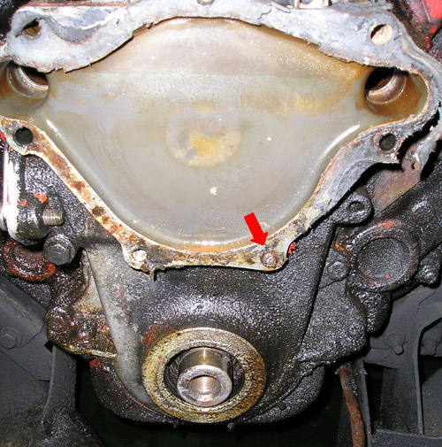
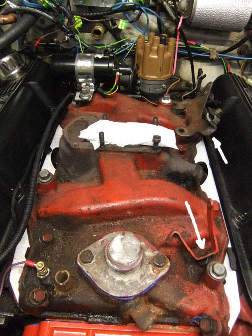
Waterpump & harmonic balancer are removed. If you look closely, you can see the broken bolt at the bottom right corner (red arrow).
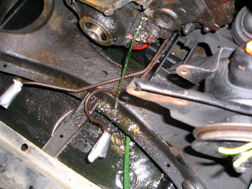
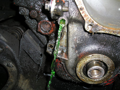
I was already wondering where the rest of the coolant was. I had already ~2.6 gallon in jerrycans. So where was the rest?
I know now ;-) ...
When I took out the last two bolts of the front cover, i found out where the last gallon was. Luckily I didn't remove the drain pan.
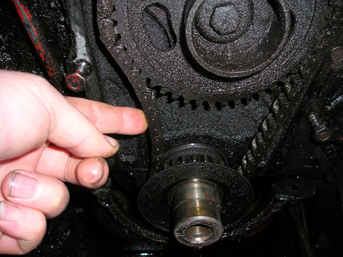
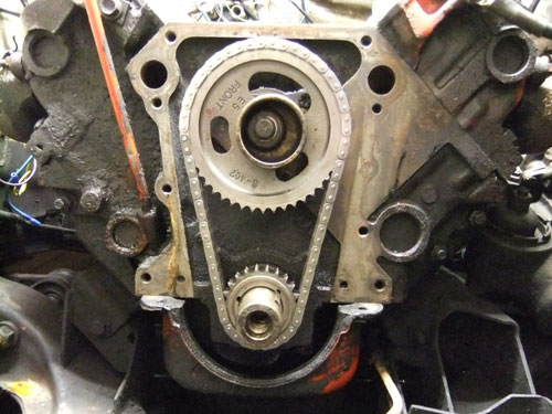
Finally the timing cover came off, after some hits with a rubber hammer. It's good I have a new timing set! This set had it's best time a couple of years ago...
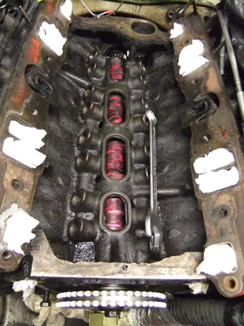
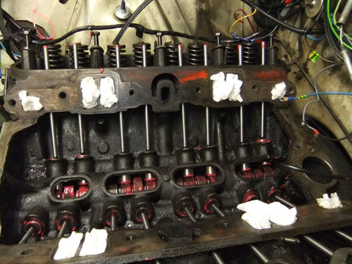
Removed left valve cover. Trying to get the lifters out, without removing the intake.
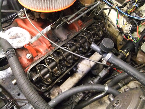
Removed left rocker arm assembly, pushrods and lifters. With a special lifter removal tool, I successfully removed the lifters. You have to do this carefully.
If you drop a lifter, you have to remove the intake...
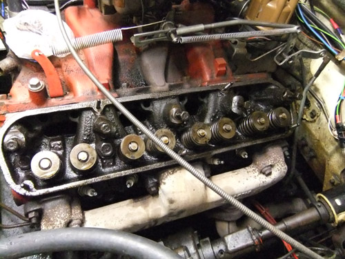
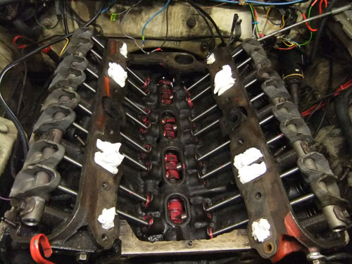
Removed passenger side rocker arm assembly. Unfortunately one of the lifters from cylinder 3 didn't want to come out and none of cyl. 7.
That means I have to take off the intake. Where I'm afraid of is the vacuum connection which feeds the heater valves under the dash.
I think originally it was a hose of some kind. Now it's almost as brittle as porcelain.
Sorry, no pictures unfortunately. I've removed almost all hoses & cables which are connected to the intake. Also the distributor and oil-pressure send unit. The dizzy has to move to remove the oilpump shaft. The oil send unit has to move because it's so big it's blocking the removal of the intake. The fuel and vacuum hoses are still connected. They will be cut when I remove the intake.
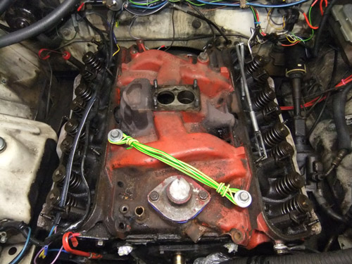
Last miniute decision, I removed the carb & LPG-mixer. Because I have to whack the intake with a big hammer and a piece of wood, to get it loose.
A makeshift handle, to lift the heavy iron intake off the engine. After I made this picture,
I made another handle between one of the coil mounting points and one of the carb studs.
Oh boy, this thing is heavy!
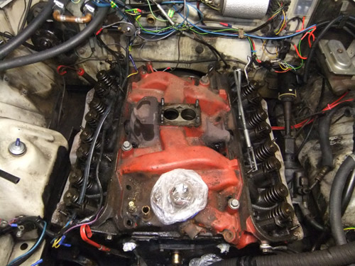
After a couple of firm hits with a big hammer (on a piece of wood at the front of the intake) it came loose. One of the gaskets came off.
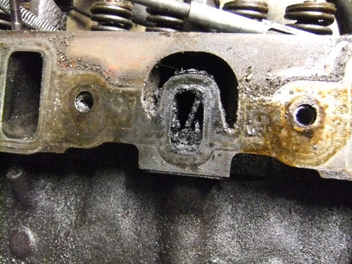
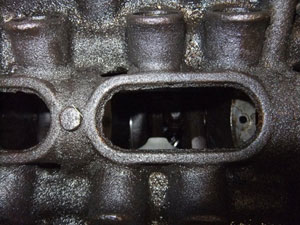
One of the heat crossover ports. Nice and clean ;-). Doesn't matter, this means less heat under the plenum.
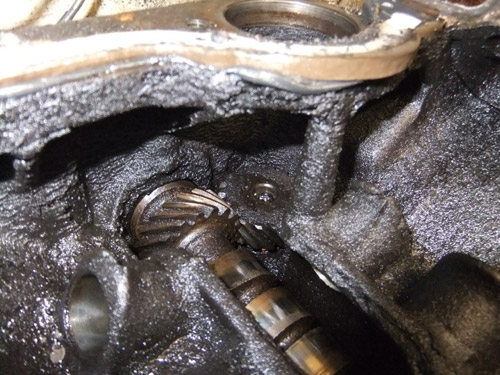
One advantage, when the intake is removed, you can easily remove the oilpump shaft. Yes, it looks a bit dirty.
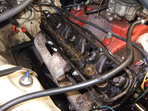
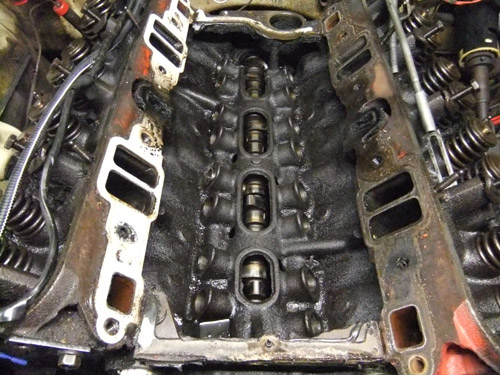
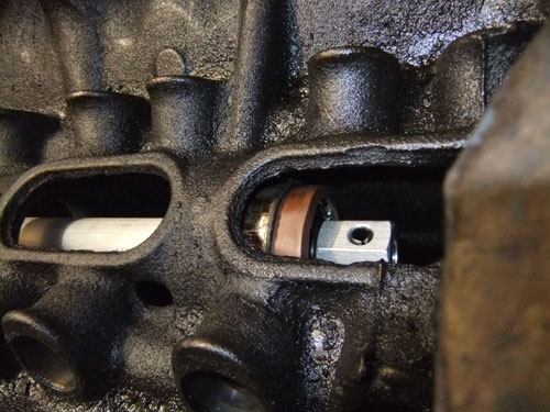
You can see two lifters which are still in the bores. And one, top right corner, which became stuck while removing. I couldn't get them out the easy way.
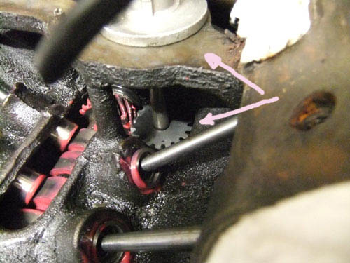
This is the reason why the intake has to came off.
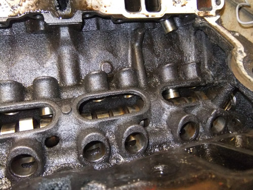
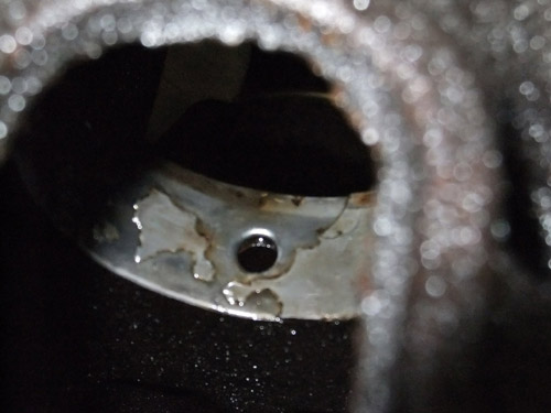
At least two of the cam bearings are shot. So I have to deal with that first...
I am happy I couldn't get some of the lifters out and had to remove the intake. Otherwise I didn't know that the camshaft bearings had to be replaced.
 The number 5 bearing can't be replaced without removing the engine from the car (i.e. detaching it from the bellhousing).
The number one bearing is probably too wide to get out of the engine via the oval holes in the valley.
The number 5 bearing can't be replaced without removing the engine from the car (i.e. detaching it from the bellhousing).
The number one bearing is probably too wide to get out of the engine via the oval holes in the valley.
 The numbers 2, 3 & 4 are small enough to fit through these valley holes.
The number one bearing goes via the crank into the oil pan.
The numbers 2, 3 & 4 are small enough to fit through these valley holes.
The number one bearing goes via the crank into the oil pan.
After disassembling a lot of the front end, i.e. the grille, the vertical support and taping the grille frame to the bumper,
I finally could insert the cam bearing tool. And even that wasn't enough, I had to remove even more!
Here you see the number four bearing almost out of the bore.
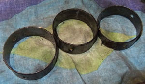 The number two, three and four bearings are out.
I could take them easily out via the valley holes.
The number one bearing is more difficult. It can't go via the valley hole.
Finally, the number one bearing is out!
After some failed attempts to remove the first bearing, I succeeded with a rather
easy solution. I simply removed the bearing by tapping it into the block (with the bearing removal tool). Then I turned the crank
in such a way there was enough room for the bearing to pass the crank and drop into the oil pan.
Because the timing cover is still removed, it's relatively easy to take out the bearing from the oil pan.
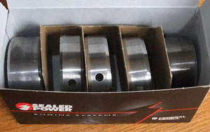
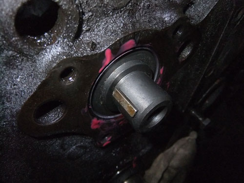
The new number one cam bearing is home. That meant I could insert the new Edelbrock camshaft! But during clean up, of the new cam, I noticed there
was no key inserted. So I had to use the old one. After some firm hits, with a soft hammer, the key was in.
Just note, I put the key into the cam, when the cam was still out of the engine!
The new camshaft in it's new home. And it spins smoothly! That means the new cam bearings are inserted straight.
So the new camshaft bearing installation & removal tool was a good investment ;-).
The new lifters and pushrods are installed.
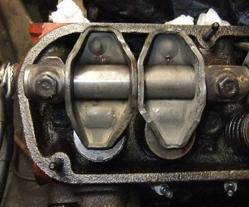
New rockershafts and rockers, on both sides.
If you don't know it, you can't see that the rockers from the intake and exhaust valves are different.
I didn't know this until I ordered the new rockers.
New timingset installed. Because I discarded the mechanical fuel pump, I didn't want to install the fuel pump eccentric.
But it seems the cup washer isn't deep enough to put the cam sprocket at it's place. The eccentric is made from 4 mm (0.16") thick metal.
So I had to use it anyway.
Installed the waterpump and timing cover. What a bitch! I used too much RTV silicone rubber.
So when I looked into the in- and output of the waterpump I saw a lot of excess silicone rubber.
Luckily I could remove it. This had severely restricted the waterflow.
The rubber seal between the oilpan and bottom of the timing cover didn't co-operate.
I read a tip on a forum, that you can use RTV silicone instead. A very thick bead of RTV solved this problem.
The Mopar Performance timing cover bolt set (P4529256) is total shit! The bolts are too long and the threads too short! (The bolts are partially threaded)
So I had to reuse some old bolts. Maybe these bolts are for the newer aluminium waterpumps?
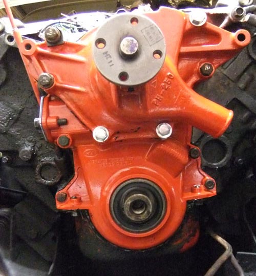
Both, timing cover & waterpump are new. The waterpump is a remanufactured unit and the timing cover is a newly made aftermarket unit. Inserted a new oil seal into the cover as well.
Oh yes, the color is RED. The photo makes it orange...
 Just a little note, I had to do it all over again. Because I didn't remember if I had torqued the camshfaft bolt. Of course when I had removed the timing cover and checked if I did, it seems I did torqued it...
So I installed the timing cover and water pump with new gaskets and very little RTV silicon sealer this time.
At least I learned something; don't use too much RTV silicone sealant!
Just a little note, I had to do it all over again. Because I didn't remember if I had torqued the camshfaft bolt. Of course when I had removed the timing cover and checked if I did, it seems I did torqued it...
So I installed the timing cover and water pump with new gaskets and very little RTV silicon sealer this time.
At least I learned something; don't use too much RTV silicone sealant!  .
.
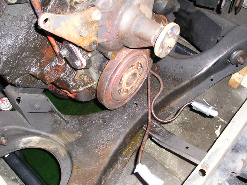
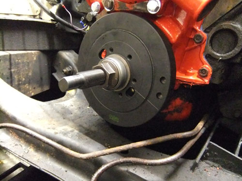
Installing the new harmonic balancer, with a special installing tool, is a breeze.
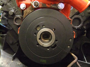 The balancer is installed.
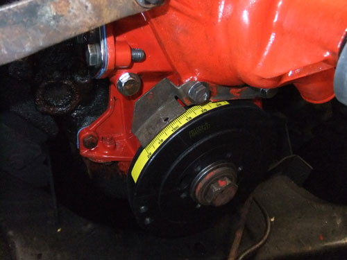
 The balancer is almost touching the molded on timing marks.
All new timing covers are made for '70 and up small blocks. Which means the timing marks are on the drivers side of the cover and molded on.
This is because the waterpump inlet is on the passenger side. But the earlier models, had the waterpump inlet on the driver side. Which means the timing marks should be on the passengers side.
The waterpump inlet and the timing marks should always be on opposite sides of each other.
If not, you can not see the timing marks, because the waterpump inlet is just above the marks and blocking the reading of it.
As you can see, on the pictures above, there is a bolted on metal timing mark on the passengers side, just above the harmonic balancer.
And that is because timing covers made in '67 had no timing marks molded onto the timing cover at all.
Temporary installed the pulleys. To check if they line up. And they do.
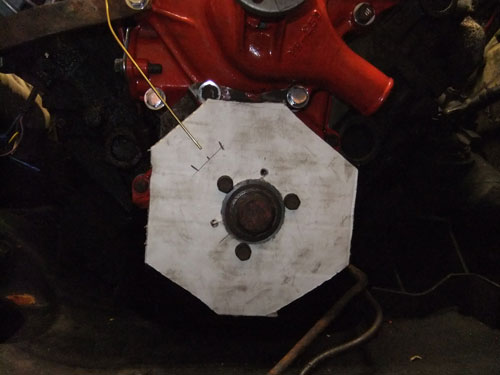
Had to make a makeshift "degree wheel". This was only to find out where TDC was. With the aid of a piston stop and looking carefully at the lifters to find out
where the compression stroke was. I was able to find true TDC.
What I already suspected, because of the post 70's timing cover (see a couple of images back). The harmonic balancer had it's zero mark (TDC) at the post '70 position (drivers side).
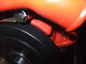
Because of this I had already ordered a self-adhesive timing tape. Oh, the engraved TDC line, on the balancer, is dead-on at the zero mark! (see white circle).
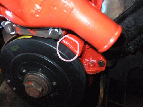
The timing tape at the, for this water pump, correct position. And to make sure, I scratched a line at that TDC position (in case the tape gets off).
Now I know where TDC is, I could install the oil pump intermediate shaft. To check if it was in the right position I temporary installed the distributor.
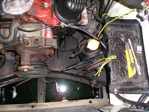
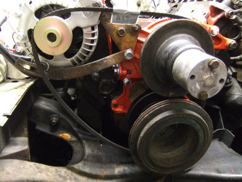
Installed the powersteering pump, alternator, crank pulleys, waterpump pulley and the fan.
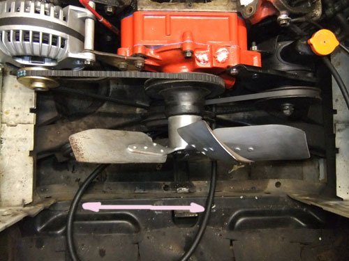
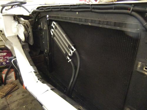
Modified the transmission cooling lines. Now it's possible to connect hoses to the new external transmission cooler (see white arrows).
Installed the old intake with some cheap gaskets. This is only for the camshaft break-in. When that is done a new Edelbrock intake will be installed.
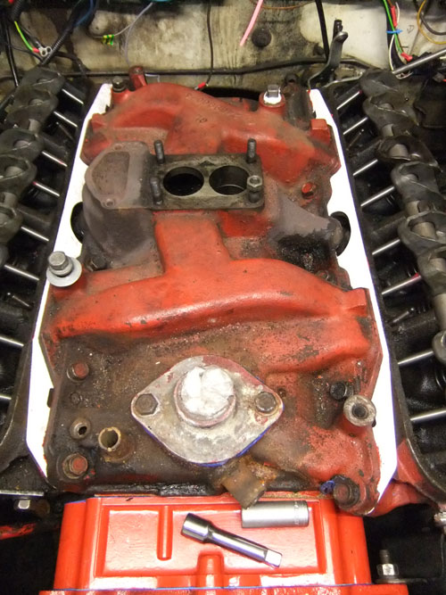
Installed the valve covers, temp. and oil-pressure sensors. The coil and distributor. Oh yeah, of course I forgot something (see 2 white arrows).
Two brackets for the throttle cable and return spring. I will install these when the RTV silicone is set.
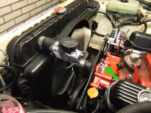
Installed the radiator and fan shroud. The upper & lower radiator hoses are not installed yet. Screwed two hose barbs into the waterpump (see green arrow)
Installed a new external transmission cooler. This was actually a future project, but the grille was out anyway, so I installed it now.
Otherwise I had to disassemble the front of the car at a later time again.
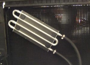 This is the smallest and cheapest transmission cooler I could find at JEGS. This cooler is not in series with the trans cooler in the radiator. I omitted that cooler.
This little transmission radiator is directly connected to the hard lines from the transmission with rubber hose.
This hose is especially made for this sort of applications, it can withstand the pressure and the nasty transmission oil.
This is the smallest and cheapest transmission cooler I could find at JEGS. This cooler is not in series with the trans cooler in the radiator. I omitted that cooler.
This little transmission radiator is directly connected to the hard lines from the transmission with rubber hose.
This hose is especially made for this sort of applications, it can withstand the pressure and the nasty transmission oil.
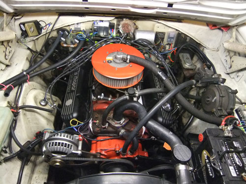
Installed all hoses, except the ones from the heater. I omitted these, for now. Now the small hoses go directly to the LPG vaporazer (seen on the right side, just above the battery).
All the fluids are in. Coolant, engine break-in oil and a little transmission oil, because my tranny leaks a little.
So everything is ready for camshaft/lifters break-in.
I shot a short video. It's a little grainy. The camera was in 640*480, instead of HD.
This is the camshaft break-in. I got the timing right, at least, for the cam break-in. Now the break-in is done, the timing can be set properly.
There was only one little problem, the lower hose at the waterpump was leaking. But this was fixed very easily.
And the neigbourhood, where I garage my car, knows my car now. Thanks to my Flowmaster 40 mufflers .
So that was it. The timing need some attention. Next step is installing the matching Edelbrock Performer intake. And discarding the carburetor in favor for LPG. But that is an other project. First I gonna move the car to a much larger garage. All this is done in a garage box, which is actually only meant for parking your car. Because of it's small size you can't comfortably wrenching in it.
Finished this project on july 9 2012 with the cam break-in.
During and after the cam break-in I noticed, that there was something wrong.
The engine was shaking very badly and it looks like a couple of cylinders didn't work.
Read all about this in the "heads and intake" page. Click the link below
See the Heads & intake page as well.